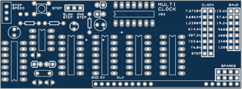


RC2014 Multi Frequency Clock
Design by: 6706
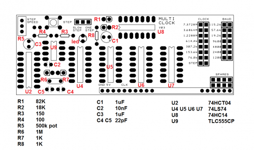
BOM and notes
Resistors:
1 x 100 (R4)
1 x 150 (R3)
2 x 1k (R7, R8)
1 x 18k (R2)
1 x 82k (R1)
1 x 1M (R6)
1 x 500k trim pot (R5)
Capacitors:
1 x 10nF (ceramic) (C2)
2 x 22pF (ceramic) (C4, C5)
2 x 1uF (electrolytic) (C1, C3)
IC:
1 x 74HCT04 (U2)
4 x 74LS74 (U4,U5,U6,U7)
1 x 74HC14 (U8)
1 x tlc555cp (U9)
Other:
1 x Crystal 7.3728MHz
1 x tactile switch p.b.
6 x 14 pin IC socket
1 x 8 pin IC socket
1 x 40 pin header 90 degree (1 x 10, 1 x 6)
1 x 40 pin double header straight (1 x 4, 1 x 7, 1 x 8)
1 x 40 pin header straight (1 x 3)
4 x links
1 x M-F jumper wire
Notes:
Designed to suit RC2014 Z80 computer by Spencer Owen http://rc2014.co.uk/
Clock circuit is the standard one for the RC2014, so you can use all the components supplied in that kit.
Note the 74 series IC types! The listed types have been tested. Using LS in place of HC (or other combinations) has not been tested but probably won't work.
Not all 555 timers are equal! An NE555 will not work! You must use a TLC555 to get a high enough output voltage.
NE555 timers:
- Almost certainly do not have the required 'rail-to-rail' output
- Use about 100 times as much power