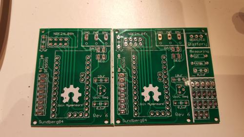
SundbergMYS7Dirty.zip
Design by: sundberg84
This is a PCB that only contains the basic functions for MySensors but is somewhat dynamic. The main goal was to eliminate the build time soldering wires between the Arduino Pro Mini and the Radio. Its a PCB for all newbies that wants to do basic nodes like myself out there... :)

Why?
So pretty much is this PCB for all newbies that only wants the basic part of MySensors documented in the website! This cuts my work with one node from a couple of hours soldering wires to 20-30min
What?
Only easy to solder components (bigger components with legs) Only basic functions (Pro Mini, Radio, Input for sensors and if battery powered booster and voltage divider) Dynamic in what power you use (Battery, 5v or Raw pin). Some inputs for all the normal sensors used in the build section. 5x5 or 3x5 depending on function
How?
Battery 3.3v
5x5cm
- Pro Mini 3.3V
- Radio with 4.7uf Cap
- Voltate divider
- Booster (0.9 - 3v > 3.3v)
- Caps/Resistors/Pinhead (jumper)/Screw terminal (optional)
- Sensors are possible to attach to the left (Gnd x 2, VCC, D3 (with or w.o resistor), D4, D5, A4, A5) I have now added labels on the sensors pin which isnt in the picture

Regulated 5v
3x5cm (cut PCB)
- Pro Mini 5v
- Radio with 4.7uf Cap
- 5v -> 3.3v Regulator with caps
- Caps/Resistors/Pinhead (jumper)/Screw terminal (optional)
- Sensors are possible to attach to the left (Gnd x 2, VCC, D3 (with or w.o resistor), D4, D5, A4, A5)

6-12v to RAW pin
3x5cm (cut PCB)
Pro Mini 5v Radio with 4.7uf Cap
- 5v -> 3.3v Regulator with caps
- Caps/Resistors/Pinhead (jumper)/Screw terminal (optional)
- Sensors are possible to attach to the left (Gnd x 2, VCC, D3 (with or w.o resistor), D4, D5, A4, A5)


